Description
SPECIFICATIONS
Brand Name: Stlxy
Origin: Mainland China
DIY Supplies: ELECTRICAL
Display Size: 3.0 - 4.9 Inches
Model Number: ZK-PP1K
Choice: yes
semi_Choice: yes
1.PWM signal generator, square wave rectangular wave signal generator
2. Used to generate a square wave rectangular wave signal, which is supplied to a DC motor or a stepper motor driver; Stepper motor, servo motor, electric gripper, robot arm
3. Combine the driver to realize dimming, speed regulation, control solenoid valve, etc. However, it is not possible to directly drive loads such as electric lights, motors, and solenoid valves
1. Highlights:
1.1 Two modes can be selected:
PWM mode - frequency (continuous), duty cycle.Note that the number of pulses cannot be set in this mode, and the pulse is always emitted;
PULSE mode - positive pulse width time, negative pulse width time, delayed start time, and adjustable number of pulses.
1.2 With start-stop button, external switch can also be used to control output signal ON/OFF.
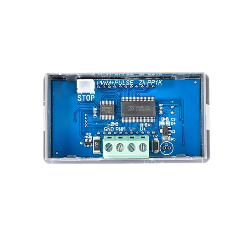
1.3 Wide voltage input 3.3-30V, with anti-reverse protection, 5.08mm terminal wiring
2. Technical parameters:
2.1 Working voltage: 3.3~30V, with anti-reverse protection
2.2 Frequency range: 1Hz~150KHz, accuracy about 1%
2.3 duty cycle range: 0-100%, 1% stepping
2.4 number of pulses: 1-9999, or infinite (display \'----\' stands for infinity)
2.5 delay output time: 0.000s-9999s, the minimum can be set 1ms
2.6 positive and negative pulse width length: 0.000s-9999s, the minimum can be set 1ms
2.7 signal loading capacity: less than 30mA
2.8 Output signal amplitude: amplitude is equal to the supply voltage
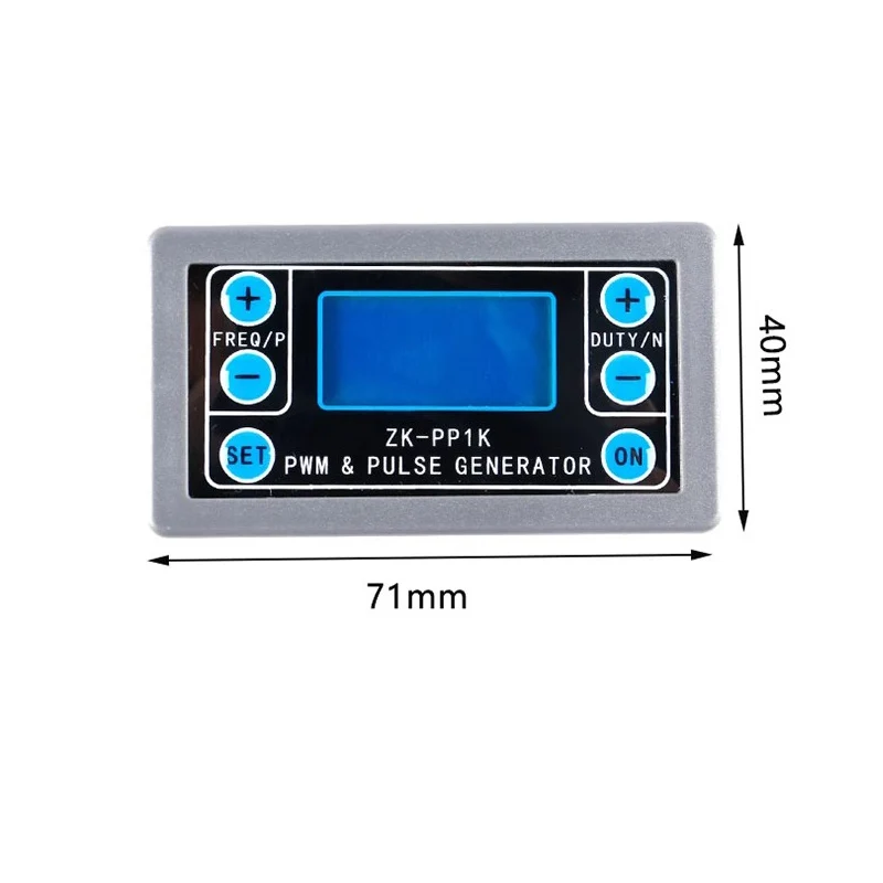
2.9 Product size: 79mm*43mm*30mm
2.10 Product Weight: 40g
2.11 Packing: Anti-static bag
3. Module description:
3.1 button operation instructions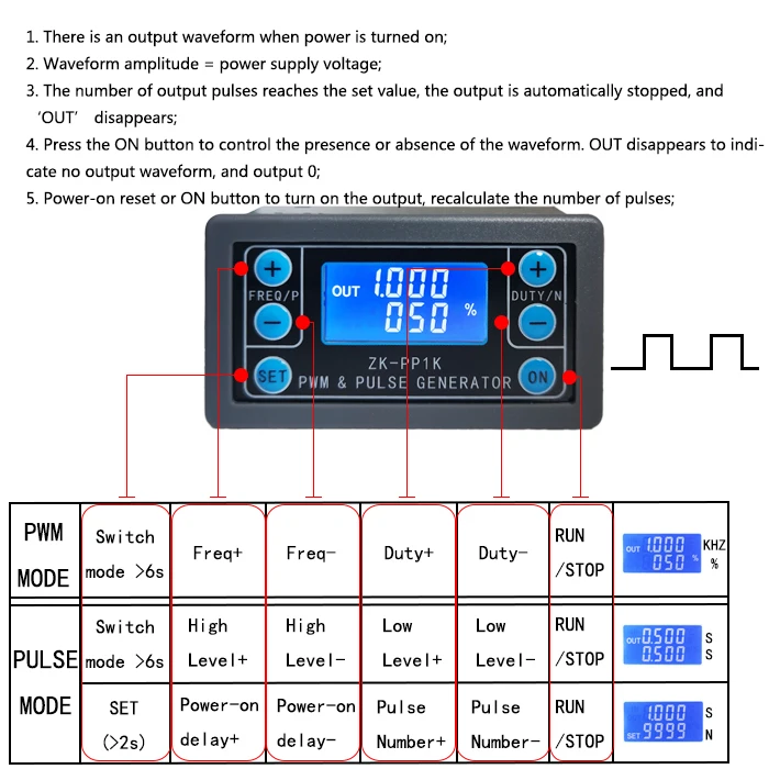
3.2 PWM mode (display has "%" for PWM mode)
The factory default mode is PWM mode, FREQ+ and FREQ-key set frequency, DUTY+ and DUTY-button set duty cycle; short press ON button control signal output or stop, stop output is 0, the screen displays "OUT" mark as There is output, otherwise it stops output; the default factory frequency is 1KHZ and the duty cycle is 50%.
If you want to switch to PULSE mode, long press the SET button (more than 6 seconds), do not release, you will see the screen change, "%" disappears, it is PULSE mode.
3.3 PULSE mode (No "%" on the right side of the display is PULSE mode)
The line above the LCD screen displays the positive pulse width time. The P+ and P- buttons set the parameter. The line below the LCD screen displays the negative pulse width time. The N+ and N- buttons set the parameter. Press the ON button to control the signal output or stop. When the output is stopped, the output is 0. The screen displays "OUT" for output, otherwise it stops output; the default factory positive pulse width is 0.5 seconds and the negative pulse width is 0.5 seconds.
Pulse number and delay time setting - In PULSE mode, press and hold the SET button for 2 seconds and then release, enter the pulse number and delay time setting interface, the screen displays SET, it will be turned off and cleared after entering. ;P+ and P- buttons set the delay time, N+ and N- buttons set the number of pulses, the factory default delay time is 0 seconds, the number of pulses is infinite (display ----); then press SET button 2 In seconds, it will automatically return to the pulse interface, press the ON button, after the delay setting time, start to issue the set number of pulses. If the number of pulses is sent, it will automatically output 0. If the period is not sent, pressing the ON button will turn off. The output pulse is turned off and cleared, and the set number of pulses is issued each time it is started. After the number of pulses is sent, the display \'OUT\' automatically disappears.
3.4 Application Operation Examples
3.4.1 PWM output 20KHZ, 60% duty cycle: Select PWM mode, the frequency is set to 20.00, and the duty ratio is set to 060%.
3.4.2 The output is turned on for 0.6 seconds and turned off for 0.2 seconds. Infinite loop: select PULSE mode, the positive pulse width is set to 0.600, the negative pulse width is set to 0.200, the delay time is set to 0.000, and the number of pulses is set to --- -.
3.4.3 Power on or press the start button, delay 5 seconds, then the output is turned on for 0.6 seconds, off 0.2 seconds, infinite loop: select PULSE mode, positive pulse width is set to 0.600, negative pulse width is set to 0.200, delay The time is set to 5.000 and the number of pulses is set to ----.
3.4.4 Power on or press the start button, delay 5 seconds, then output high level 10ms low level 10ms pulse 100: select PULSE mode, positive pulse width is set to 0.010, negative pulse width is set to 0.010, delay The time is set to 5.000 and the number of pulses is set to 0100.
3.4.5 Power-on delay for 10 seconds, then permanently output signal: select PULSE mode, the positive pulse width is set to a number greater than 0, the negative pulse width is set to 0, the delay time is set to 10.00 seconds, and the pulse number is infinite. (----).
3.4.6 Other applications can explore or consult customer service
All setup parameters are not lost when they are turned off.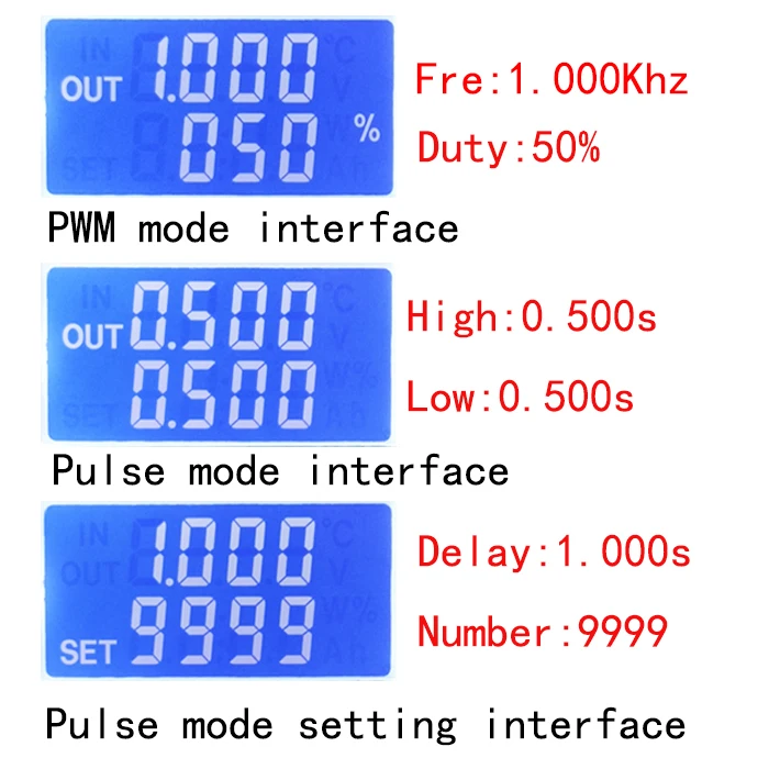
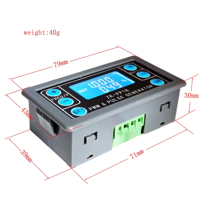
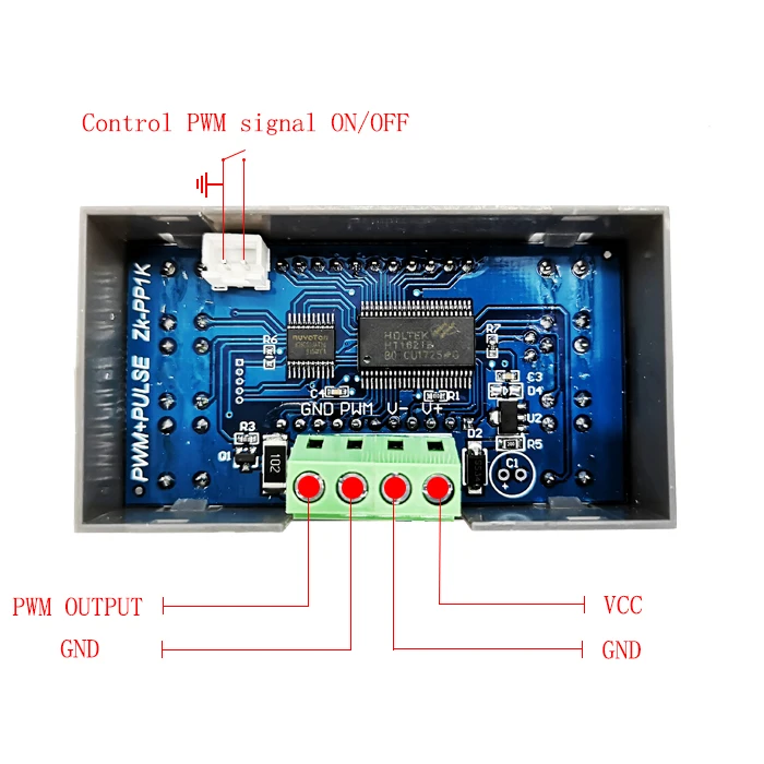
1.Description:
ZK-PP2K signal generator is a device that provides electrical signals at a variety of frequencies, square wave,pulse and output levels.It supports dual mode:PWM mode and PULSE mode.It supports high current output and can be directly connected to the motor.It is used as a signal source or excitation source for testing.Widely used in production practice and technology.
2.Features:
1>.Dual mode:PWM mode and PULSE mode
2>.LCD high definition display
3>.Support frequency adjustment
4>.Support duty cycle adjustment
5>.High precision detection
6>.Support power-down memory function
7>.1-Channel signal output
8>.Support reverse protection
9>.Support enabled/disabled output
10>.Direct drive LED/Motor/solenoid valve
3.Parameters:
1>.Product name: ZK-PP2K PWM Signal Generator
2>.Model: ZK-PP2K
3>.Work voltage:DC 3.3V-30V
4>.Frequency range:1Hz~150KHz
5>.Frequency accuracy:2%
6>.Duty cycle range:0.00%-100%
7>.Output Current:8A(Max)
8>.Number of pulses:1~9999 or Infinite
9>.Delay time:0.000s~9999s
10>.Pulse width:0.000s~9999s
11>.Time accuracy:1ms
12>.Output amplitude:Same to input voltage
13>.Work Temperature:-20℃~85℃
14>.Work Humidity:0%~95%RH
15>.Size:79*43*26mm
4.Work Mode:
1>.PWM Mode:Frequency,Duty cycle
1.1>.It is PWM mode when display ‘%’.
1.2>.The factory default mode is PWM mode.
1.3>.Button FREQ+ and FREQ- are used to setting output frequency.User can short press by set value in minimum unit or keep press to continuous setting. Frequency range is 1Hz to 150KHz.
1.4>.Button DUTY+ and DUTY- are used to setting output duty cycle for frequency.User can short press by set value in minimum unit or keep press to continuous setting. Duty cycle range is 0.00% to 100%.
1.5>.Short press button ‘ON’ to enabled or disabled output.It is enabled output when display symbol ‘OUT’ on left.It is disabled output if no display symbol ‘OUT’ and module will output 0V.
1.6>.The default factory frequency is 1KHz and the duty cycle is 50%.
1.7>.Switch work mode:Keep press button ‘SET’ about 6 second.Then it is enter into PULSE mode if symbol ‘%’ disappear on right.
2>.PULSE Mode:Pulse width,Delay,Pulse number
2.1>.It is PWM mode without display symbol ‘%’.
2.2>.Button P+ and P- are used to set time for positive pulse width.Displayed on the first line.Set time range is 0.000s~9999s.
2.3>.Button N+ and N- are used to set time for negative pulse width time.Displayed on the second line.Set time range is 0.000s~9999s.
2.4>.Short press button ‘ON’ to enabled or disabled output.It is enabled output when display symbol ‘OUT’ on left.It is disabled output if no display symbol ‘OUT’ and module will output 0V.
2.5>.The default factory positive pulse width is 0.5 seconds, and the negative pulse width is 0.5 seconds.
2.6>.Long press button ‘SET’ for 2 seconds to enter into set the number of pulses and delay time.Screen will display symbol ‘SET’ at lower left corner. Note:Once in this mode,the output will be disabled and output pulse will be cleared.
2.7>.Button P+ and P- are used to set delay time.Set time range is 0.000s~9999s.
2.8>.Button N+ and N- are used set the number of pulses.Set range is 1~9999 or Infinite.
2.9>.The factory default delay time is 0 seconds, and the number of pulses is infinite (display ‘----’).
2.10>.Automatic return to pulse interface by press button ‘SET’ for 2 seconds.
2.11>.Short press button ‘ON’ to after set delay time and then start output the set number of pulses.
2.12>.It will automatically output 0V if the number of pulses is sent.The output will be disabled and clear pulse numbers if press button ‘ON’ during output.
2.13>.The number of set pulses is output each time when module power on and then stop output or press button ‘ON’ to restart.
5.Practical application:
1>.PWM output 20KHz,60% : Select PWM mode.Set frequency to 20.00 and duty cycle to 060%.
2>.Output turn ON 0.6s,OFF 0.2s,infinite loop : Select PULSE mode.Set positive pulse width to 0.600 and negative pulse width to 0.200.Delay time to 0.000.Number of pulses to ‘----’.
3>.Delay 5s after power ON or press ‘ON’ button.Then output turn ON 0.6s,OFF 0.2s,infinite loop : Select PULSE mode.Set positive pulse width to 0.600 and negative pulse width to 0.200.Delay time to 5.000.Number of pulses to ‘----’.
4>.Delay 5s after power ON or press ‘ON’ button.Then output 10ms high level signal,10ms low level signal,cycle 100 times : Select PULSE mode.Set positive pulse width to 0.010 and negative pulse width to 0.010.Delay time to 5.000.Number of pulses to 0100.
5>.Delay 5s after power ON.Then keep output : Select PULSE mode.Set positive pulse width more than 0(any value) and negative pulse widt